eZ Components - Workflow - Theoretical Background
Table of Contents
Introduction
This document contains theoretical background information on the Workflow engine. It is an excerpt from Sebastian Bergmann's diploma thesis.
Workflow Patterns
In Chapter 3 of his PhD thesis, Kiepuszewski lists requirements for workflow languages through workflow patterns.
Much like the software design patterns, these workflow patterns describe recurring solutions to common problems. They are relevant to both the implementor and the user of a workflow management system. The former uses the workflow patterns as a common vocabulary for workflow description language constructs and to define the semantics of a workflow model whereas the latter uses them as a guide while formulating his workflow in the workflow system's description language. The workflow patterns also faciliate the comparison with other workflow systems with regard to expressiveness and power.
In Chapter 4 of his PhD thesis, Kiepuszewski maps the workflow patterns that he identified to Petri nets to provide a formal foundation for this more pragmatic approach to defining workflow semantics.
In this section we discuss the subset of the workflow patterns identified by Kiepuszewski that is directly supported by the Workflow component.
Basic Control Flow Patterns
The workflow patterns for basic control flow capture elementary aspects of process control and closely match the definitions of elementary control flow concepts provided by the Workflow Management Coalition in [WfMC95, WfMC99].
Sequence
The Sequence workflow pattern represents linear execution of workflow steps: one action of a workflow is activated unconditionally (for example B the figure below) after another (for example A in the figure below) finished executing.
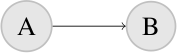
Use Case Example: After an order is placed, the credit card specified by the customer is charged.
Parallel Split (AND-Split)
The Parallel Split workflow pattern divides one thread of execution (for example the one that activates A in the figure below) unconditionally into multiple parallel threads of execution (for example the ones that start in B, C, and D in the figure below).
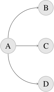
Use Case Example: After the credit card specified by the customer has been successfully charged, the activities of sending a confirmation email and starting the shipping process can be executed in parallel.
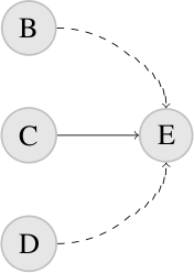
Synchronization (AND-Join)
The Synchronization workflow pattern synchronizes multiple parallel threads of execution (for example the ones that end in B, C, and D in the figure below) into a single thread of execution (for example the one that starts in E in the figure below).
Workflow execution continues once all threads of execution that are to be synchronized have finished executing (exactly once).
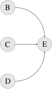
Use Case Example: After the confirmation email has been sent and the shipping process has been completed, the order can be archived.
The workflow patterns that have been discussed so far handle the unconditional routing of control flow. We will now take a look at the workflow patterns for conditional routing.
Exclusive Choice (XOR-Split)
The Exclusive Choice workflow pattern defines multiple possible paths (for example the ones that start in B, C, and D in the figure below) for the workflow of which exactly one is chosen (for example the one that starts in C in the figure below).
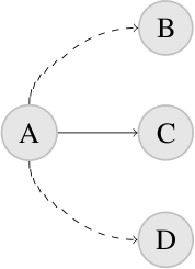
Use Case Example: After an order has been received, the payment can be performed by either credit card or bank transfer.
Simple Merge (XOR-Join)
The Simple Merge workflow pattern is to be used to merge the possible paths that are defined by a preceding Exclusive Choice. It is assumed that of these possible paths exactly one is taken (for example C in the figure below) and no synchronization takes place.
Use Case Example: After the payment has been performed by either credit card or bank transfer, the order can be processed further.
Advanced Branching and Synchronization
The workflow patterns for advanced branching and synchronization do not have straightforward support in most [of the] workflow engines [that Kiepuszewski evaluated]. Nevertheless, they are quite common in real-life business scenarios.
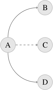
Multi-Choice (OR-Split)
The Multi-Choice workflow pattern defines multiple possible paths (for example the ones that start in B, C, and D in the figure below) for the workflow of which one or more are chosen (for example the ones that start in B and D in the figure below). It is a generalization of the Parallel Split and Exclusive Choice workflow patterns.
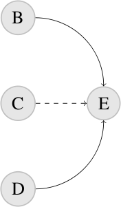
Synchronizing Merge
The Synchronizing Merge workflow pattern is to be used to synchronize multiple parallel threads of execution that are activated by a preceding Multi-Choice (for example the ones that end in B and D in the figure below).
Discriminator
The Discriminator workflow pattern can be applied when the assumption we made for the Simple Merge workflow pattern does not hold. It can deal with merge situations where multiple incoming branches may run in parallel.
It activates its outgoing node after being activated by the first incoming branch and then waits for all remaining branches to complete before it resets itself. After the reset the Discriminator can be triggered again.
Use Case Example: To improve response time, an action is delegated to several distributed servers. The first response proceeds the flow, the other responses are ignored.
Structural Patterns
The structural workflow patterns deal with restrictions that different workflow models can impose.
Arbitrary Cycles
A common restriction workflow models impose is that arbitrary cycles, ie. one or more activities are done repeatedly, are not supported. As an alternative, special loop constructs that mark the start and end point of a structured cycle are offered.
Implicit Termination
The execution of the workflow is (successfully) terminated when there are no activated activities left and no other activity can be activated. This implicit termination of workflow execution can be used in addition to explicit end activities.
Cancellation Patterns
Cancel Case
The execution of a workflow instance is cancelled.
Use Case Example: An order is cancelled.
Workflow Model
Activities and Transitions
The workflow model is activity-based. The activities that are to be completed throughout the workflow and the transitions between them are mapped to the nodes and edges of a directed graph. This choice was made to faciliate the application of the Graph-Oriented Programming paradigm for the implementation of the Workflow component. Using a directed graph as the foundation for the workflow model makes it possible to define the syntax of the workflow description language using the formalism of graph grammars.
Graph Traversal and Execution Strategy
The execution of a workflow starts with the graph's only Start node. A graph may have one or more End nodes that explicitly terminate the workflow execution.
After a node has finished executing, it can activate one or more of its possible outgoing nodes. Activation adds a node to a set of nodes that are waiting for execution. During each execution step, a node from this set is executed. When the execution of a node has been completed, the node is removed from the set.
The workflow execution is implicitly terminated when no nodes are activated and no more nodes can be activated (see the Implicit Termination workflow pattern that was discussed above).
State and Workflow Variables
The workflow model supports state through the concept of workflow variables. Such a variable can either be requested as user input (from an Input node) or be set and manipulated through the VariableSet, VariableAdd, VariableSub, VariableMul, VariableDiv, VariableIncrement, and VariableDecrement nodes.
While a VariableSet node may set the value of a workflow variable to any type that is supported by the underlying programming language, the other variable manipulation nodes only operate on numbers.
Variables are bound to the scope of the thread in which they were defined. This allows parallel threads of execution to use variables of the same name without side effects.
Wait States
When the execution of a workflow reaches an Input node (see above), the execution is suspended until such time when the user input has been provided and the execution can be resumed.
Control Flow
The control flow semantics of the workflow model draws upon the workflow patterns that were discussed above. The Sequence, Parallel Split, Synchronization, Exclusive Choice, Simple Merge, Multi-Choice, Synchronizing Merge, Discriminator, and Cancel Case workflow patterns are all directly supported by the workflow model.
Exclusive Choice and Multi-Choice nodes have branching conditions attached to them that operate on workflow variables to make their control flow decisions. A special node, named Loop, to conveniently express loops is also available.
Action Nodes and Service Objects
So far we have only discussed nodes that control the flow and that can manipulate workflow variables. We are still missing a type of nodes that actually performs an activity. This is where the Action node comes into play.
When the execution of a workflow reaches an Action node, the business logic of the attached Service Object is executed. Service Objects "live" in the domain of the application into which the workflow engine is embedded. They have read and write access to the workflow variables to interact with the rest of the workflow.
Sub-Workflows
The workflow model supports sub-workflows to break down a complex workflow into parts that are easier to conceive, understand, maintain, and which can be reused.
A sub-workflow is started when the respective Sub-Workflow node is reached during workflow execution. The execution of the parent workflow is suspended while the sub-workflow is executing. It is resumed once the execution of the sub-workflow has ended.
Design and Implementation
This section discusses the design and implementation of the Workflow component.
Architecture
The Workflow engine has been designed and implemented as four loosely coupled components. The Workflow component provides an object-oriented framework to define workflows and an execution engine to execute them. The WorkflowDatabaseTiein and WorkflowEventLogTiein components tie the Database and EventLog components into the main Workflow component for persistence and monitoring, respectively. The WorkflowSignalSlotTiein component leverages the SignalSlot component for the Workflow component's plugin system.
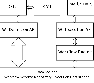
A workflow can be defined programmatically by creating and connecting objects that represent control flow constructs. The classes for these objects are provided by the Workflow Definition API. This API also provides the functionality to save workflow definitions (ie. object graphs) to and load workflow definitions from a data storage. Two data storage backends have been implemented, one for relational database systems and another for XML files. Through the Workflow Execution API the execution of a workflow definition can be started, resumed, and cancelled. The figure below shows the conceptual architecture for the workflow engine.
The idea that a workflow system should be comprised of loosely coupled components is discussed, for instance, in [DAM01, DG95, PM99]. Manolescu states that an object-oriented workflow architecture must provide abstractions that enable software developers to define and enact how the work flows through the system [DAM01].
The component-based workflow architecture Micro-Workflow encapsulates workflow features in separate components. This architecture follows the Microkernel pattern which applies to software systems that must be able to adapt to changing system requirements. It separates a minimal functional core from extended functionality and customer-specific parts. The microkernel also serves as a socket for plugging in these extensions and coordinating their collaboration [FB96].
Workflow Virtual Machine
This section proposes a so-called workflow virtual machine as the executing component of a component-based workflow architecture.
Given the fact that standardization efforts, e.g. XPDL [WfMC05] proposed by the WfMC, have essentially failed to gain universal acceptance [WA04], the problem of developing a [workflow system] that supports changes in the [workflow description language] needs to be addressed.
Fernandes et. al. propose to split the [workflow system] into two layers: (1) a layer implementing a Workflow Virtual Machine, which is responsible for most of the [workflow system] activities; and (2) a layer where the different [workflow description languages] are handled, which is responsible for making the mapping between each [workflow description language] and the Workflow Virtual Machine [SF04].
A workflow virtual machine isolates the executing part of a workflow management system, the backend, from the parts that users interact with, the frontend. This isolation allows for the definition of a backend language to describe exactly the workflows that are supported by the executer and its underlying workflow model. This backend language is not the workflow description language users use to define their workflows. They use frontend languages that can be mapped to the system's backend language.
Graph-Oriented Programming
The manual of JBoss jBPM [JBOSS], a platform for multiple process languages supporting workflow, business process management, and process orchestration, introduces Graph-Oriented Programming [as a] new implementation technique that serves as a basis for all graph-based process languages.
Graph-Oriented Programming implements the graphical representation and the wait states of a process language in an object-oriented programming language. The former can be achieved by providing a framework of node classes. Objects of these classes represent the nodes in the process graph, relations between these objects represent the edges. Such an object graph can then be traversed for execution. These executions need to be persistable, for instance in a relational database, to support the wait states.
The aforementioned node classes implement the Command design pattern and encapsulate an action and its parameters.
The executing part of the workflow engine is implemented in an Execution class. An object of this class represents a workflow in execution. The execution object has a reference to the current node. When the execution of a workflow is started, a new execution object is created and the current node is set to the workflow's start node. The execute() method that is to be provided by the node classes is not only responsible for executing the node's action, but also for propagating the execution: a node can pass the execution that arrived in the node [to] one of its leaving transitions to the next node.
Like Fowler in [MF05], the authors of the JBoss jBPM manual acknowledge the fact that current software development relies more and more on domain specific languages. They see Graph-Oriented Programming as a means to implement domain specific languages that describe how graphs can be defined and executed on top of an object-oriented programming language.
In this context, a process language (such as a workflow description language) is nothing more than a set of Node implementations. The semantics of each node are defined by the implementation of the execute() method in the respective node class. This language can be used as the backend language of a Workflow Virtual Machine (see above). In this lanugage, the workflow is represented as a graph of command objects. The workflow patterns (see above) make up the requirements for and can be mapped to the respective classes.
One of the advantages of using a domain specific language that Fowler gives in [MF05] regards the involvement of lay programmers: domain experts who are not professional programmers but program in domain specific languages as part of the development effort. In essence this means that a software system that provides a domain specific language can be customized and extended without knowledge of the underlying programming language that was used to implement it.